ESPeasy on Sonoff THR316 with temperature sensor DS18b20
Recently a pump broke that pushed hot water through the circulation in our home. For those who live in quiet old houses (like me before moving): the idea is that you open a tap for hot water and it is immediatly hot - you do not have to wait for the already cold water to flow out of the tubes, because the hot water tubes form a circle through the house that can be kept hot by letting water circulate through the heatings hot water storage.
To not have the pump running all the time (cost for power, wear) it is stopped in intervals and during times hot water is not needed.
My broken pump has (only the motor broke) electronics to let me set water temperatures to start and stop and times when it shouldn't run at all (when nobody is expected to open a hot water tap).
The controls I had never satisfied me, because depending on the energy our photovoltaic system delivers the water temperature changes and sometimes we accept it to fall below the minimum I could set in the pumps control which made the pump run all the time.
Furthermore the pump with these controls costs 350€ compared to 110€ for a pump without any controls.
I decided to use an external controler: a #esp8266 based #Sonoff TH-16 flashed with the open-source firmware #ESPeasy .
Turned out the devices are not available anymore and had been replaced by the newer, better looking esp32 based Sonoff #THR316. Similar, but not the same. Here's what I learned.
Warning
any mistake while working on 110V/230V installations can lead to serious harm:
- death, physical harm like burns, blindness
- fire
- your equipment being broken
Flashing
There are various tutorials
on how to connect to and flash new firmware to esp8266 sonoff devices which apply to the new esp32 version the same way they do to the older version.
I opened the device and soldered pins to the pcb. There are four holes for them in a row labeled GND, 3.3, TX,RX.
Important:
- Do never use the serial interface with 110/230V connected to your device
- Take care your serial adapter uses 3.3V (not 1.8V nor 5V)
- Keep in mind: flashing might work when powered from your serial adapter, but starting the flashed firmware might as well fail, because the serial adpater doesn't provide enough power
Software: esptool.py 
I used the following somewhat old version I already had installed:
$ esptool.py version
esptool.py v3.3
3.3
Erasing the flash
Before flashing ESPeasy I erased the flash as mentioned in the tutorials. In my setup I didn't need to specify any parameters for this to work. Before erasing: there's no way back to the old firmware if you erase the flash.
If you want to be able to restore the original firmware you should find out how to backup it before flashing. I didn't care and erased the flash: esptool.py erase_flash. The command worked without any extra parameters in my setup.
Flashing the firmware
Before flashing read Problems to expect below about the image you'll decide to flash.
After erasing the flash I wrote the new firmware to the flash using the following command (if you decide to use a different image replace the image name):
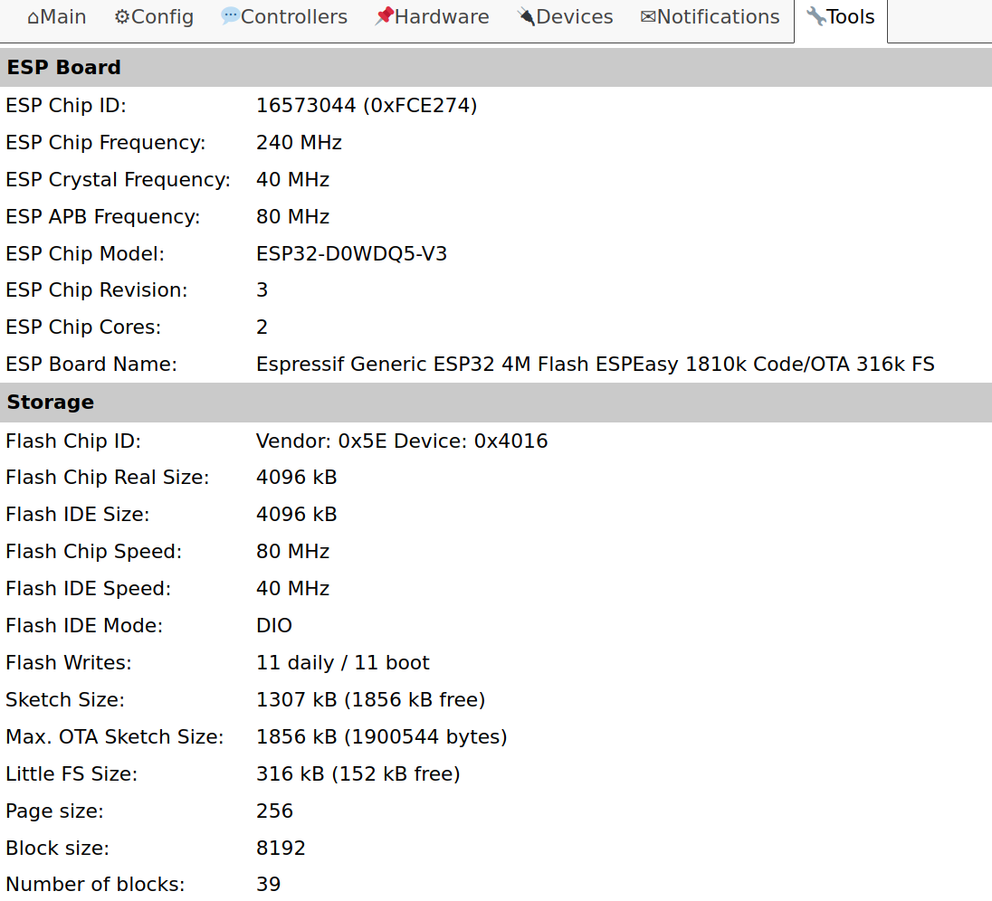
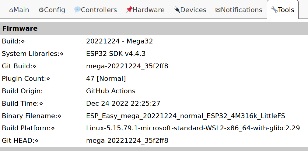
$ esptool.py --chip esp32 --before default_reset --after hard_reset write_flash -z --flash_mode dio --flash_freq 80m --flash_size detect 0x0 ESP_Easy_mega_20221224_normal_ESP32_4M316k_LittleFS.factory.bin
Problems encountered
Before the setup worked for me I tried a different firmware image (ESP_Easy_mega_20221224_normal_ESP32_4M316k.factory.bin), configured it, found the temperature sensor #DS18b20 working, moved the device from my desk to its final location and - no DS18b20 anymore. Didn't find any way to make it talk to the sensor again. I tried a different sensor and that one didn't work neither.
I had to get the THR316 back on my desk, open it up, flash it again using a different firmware (the one in the command above) and configured it again. After that it worked as expected - also after moving out of my office.
I didn't find the reason for this to happen, but you can read about another persons experience on the LETS CONTROL IT forum.
One of the devs of ESPeasy already replied to my comment mentioning that using a newer build would help to avoid this experience.
A big THANK to the devs building this great software!
Configuration
To configure the device I had to disconnect the serial adapter and connect it to the 230V power. I took care not to mix up phase and neutral and connected them exactly as printed on the case of the THR316. Only on 230V the device booted.
Wifi
The AP for initial configuration showed up as ESP-Easy and I connected using the password configesp.
Using http://192.168.4.1/ on the computer connected to the ap of the THR316 I configured the connection to my internal #iot wifi.
After that the device could be reached from the same IP subnet on its final IP on my iot wifi. To be able to access the device from a different IP subnet Client IP block filtering needs to be configured accordingly.
GPIOs
To configure the device the information about the GPIOs is needed to tell ESPeasy where the button, leds and sensor are connected.
The information can be found on the Tasmota page for the THR316.
If you do not want to flash yourself and you'd be happy to use your THR316 or similar device via MQTT-only read about Tasmota and order an already flashed device.
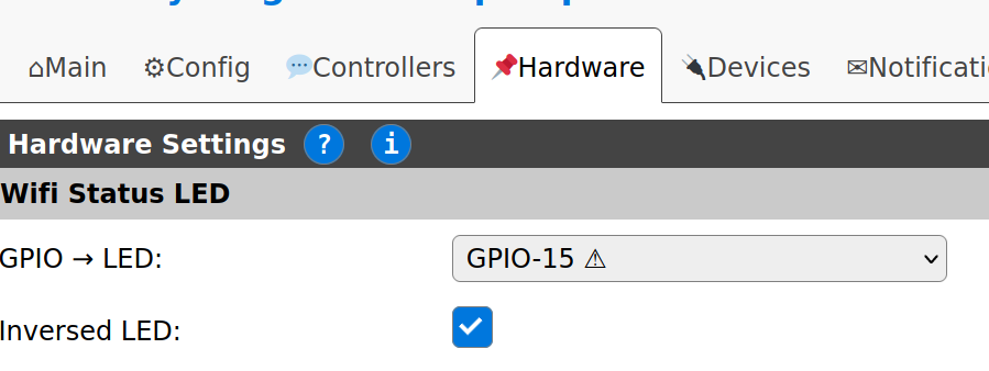
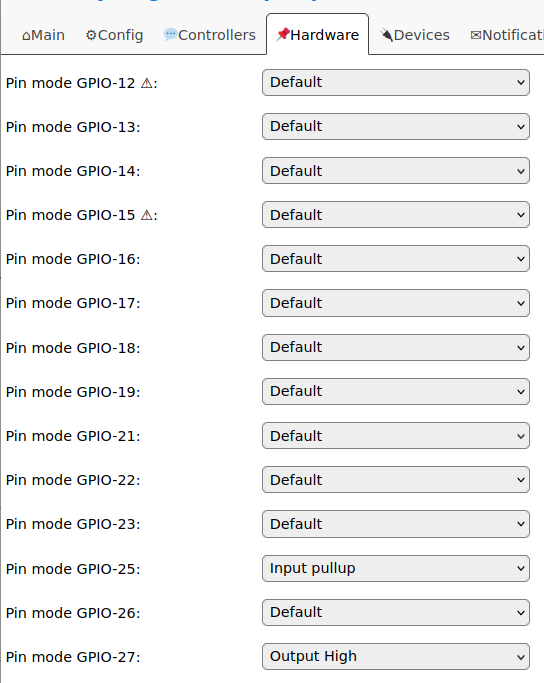
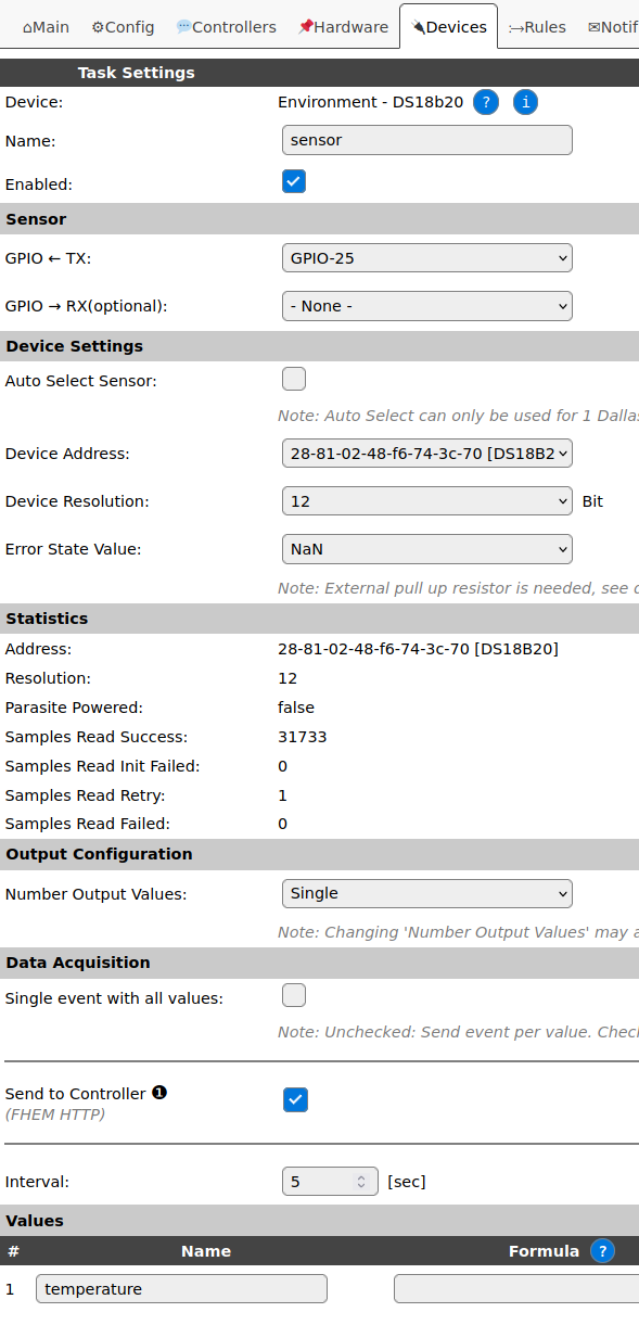
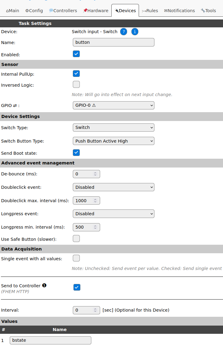
These are the GPIOs I used:
- 13: Auto LED
- 15: Wifi LED
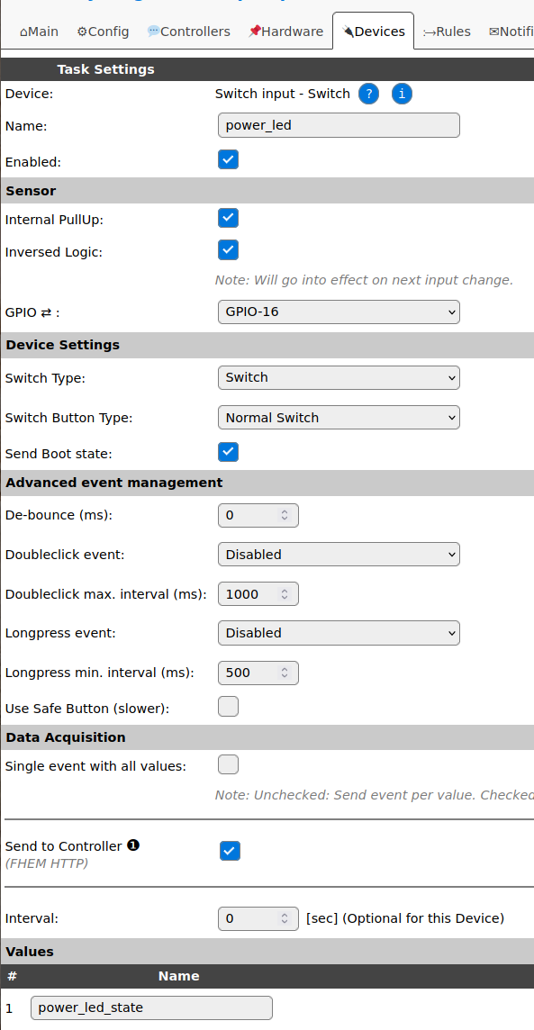
- 16: Power LED
- 21: Relay
- 25: Sensor input (DS18b20)
- 27: additional power for the sensor
basic settings
The settings I made through the webgui can be found in the screenshots below.
rules
Rules can be used to program ESPeasy devices. They can be used for simple tasks like initial setup or acting on a connected push button by switching a relay or even complexer ideas like letting neopixels glow dependend on noise level.
To use rules they need to be enabled in Tools/Advanced/Rule Settings. After enabling Rules a new tab appears in the web gui called →Rules.
I wrote some rules for the button, relay and power and auto led on the THR316:
// on boot switch power led on
on System#Boot do
  GPIO,16,0
endon

// on event "switch" toggle the relay and the auto led
on switch do
  if [auto_led#auto_led_state]=1
    gpio,21,0
    gpio,13,1
  else
    gpio,21,1
    gpio,13,0
  endif
endon

// when the button is pushed trigger event "switch"
on button#bstate do
  event switch
endon

// used to be triggered externally to switch on the relay and the auto led
on switch_on do
    gpio,21,1
    gpio,13,0
endon

// used to be triggered externally to switch off the relay and the auto led
on switch_off do
    gpio,21,0
    gpio,13,1
endon
what else?
Using this basic setup I integrated the THR316 into my existing #FHEM setup.
The setup already integrates information gathered from our heat pump. Now I can design custom rules to let the new pump run only when needed and make its operation dependend on the temperatures to be exepected in the hot water circulation.
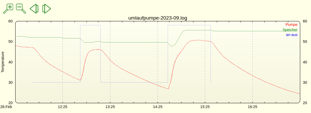
I appended a first simple diagram showing the heatings hot-water tank temperature, the temperature at the pipe where the water returns from the circulation and a blue line showing the times the pump has been switched on.
Based on these informations I can tune the rules to automatically enable and disable the new pump.
After having good rules I could probably even implement them directly in ESPeasy to make the pumps controller independent of its FHEM integration.
- ~200€ cheaper than replacing the broken pump by one with integrated controls
- open - I can make it do exactly what I expect
- learned new stuff
- the pump really belongs to me, because I repaired it (Self-Repair Manifest)

